WHAT I KNEW?
All i know about capacitor is that it stores energy. When talking about capacitor we can also touch about the capacitance which is the one that permits the storage of energy.
WHAT I LEARNED?
A capacitor is a two-terminal, electrical component. Along with resistors and inductor, they are one of the most fundamental passive components we use. You would have to look very hard to find a circuit which didn’t have a capacitor in it.
Capacitor is a passive electronic component that stores energy in the form of an electrostatic field. In its simplest form, a capacitor consists of two conducting plates separated by an insulating material called the dielectric.

How a Capacitor Is Made
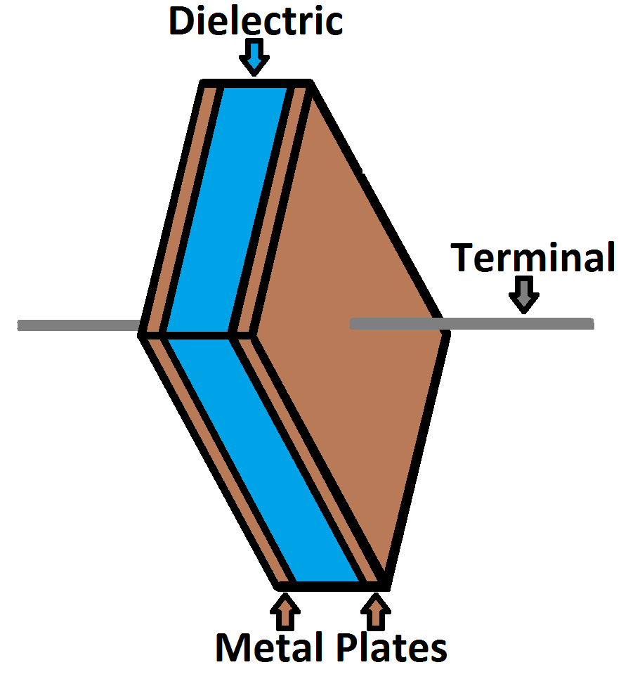
The schematic symbol for a capacitor actually closely resembles how it’s made. A capacitor is created out of two metal plates and an insulating material called a dielectric. The metal plates are placed very close to each other, in parallel, but the dielectric sits between them to make sure they don’t touch.
Calculating Charge, Voltage, and Current
A capacitor’s capacitance – how many farads it has – tells you how much charge it can store. How much charge a capacitor is currently storing depends on the potential difference (voltage) between its plates. This relationship between charge, capacitance, and voltage can be modeled with this equation:

Charge (Q) stored in a capacitor is the product of its capacitance (C) and the voltage (V) applied to it.
The capacitance of a capacitor should always be a constant, known value. So we can adjust voltage to increase or decrease the cap’s charge. More voltage means more charge, less voltage…less charge.
That equation also gives us a good way to define the value of one farad. One farad (F) is the capacity to store one unit of energy (coulombs) per every one volt.
Calculating Current
We can take the charge/voltage/capacitance equation a step further to find out how capacitance and voltage affect current, because current is the rate of flow of charge. The gist of a capacitor’s relationship to voltage and current is this: the amount of current through a capacitor depends on both the capacitance and how quickly the voltage is rising or falling. If the voltage across a capacitor swiftly rises, a large positive current will be induced through the capacitor. A slower rise in voltage across a capacitor equates to a smaller current through it. If the voltage across a capacitor is steady and unchanging, no current will go through it.
The equation for calculating current through a capacitor is:
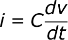
The dV/dt part of that equation is a derivative (a fancy way of saying instantaneous rate) of voltage over time, it’s equivalent to saying “how fast is voltage going up or down at this very moment”. The big takeaway from this equation is that if voltage is steady, the derivative is zero, which means current is also zero. This is why current cannot flow through a capacitor holding a steady, DC voltage.
Capacitors in Series/Parallel
Much like resistors, multiple capacitors can be combined in series or parallel to create a combined equivalent capacitance. Capacitors, however, add together in a way that’s completely the opposite of resistors.
Capacitors in Parallel
When capacitors are placed in parallel with one another the total capacitance is simply the sum of all capacitances. This is analogous to the way resistors add when in series.
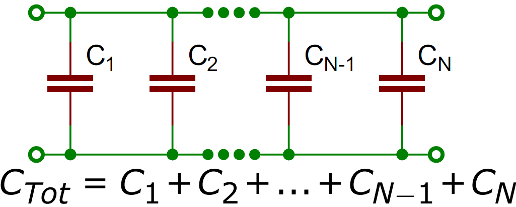
So, for example, if you had three capacitors of values 10µF, 1µF, and 0.1µF in parallel, the total capacitance would be 11.1µF (10+1+0.1).
Capacitors in Series
Much like resistors are a pain to add in parallel, capacitors get funky when placed in series. The total capacitance of Ncapacitors in series is the inverse of the sum of all inverse capacitances.
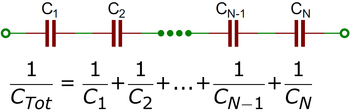
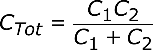
If you only have two capacitors in series, you can use the “product-over-sum” method to calculate the total capacitance:
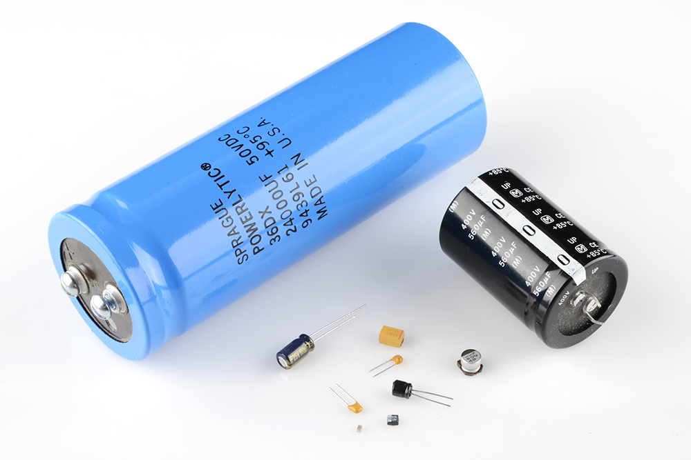
Types of Capacitors
There are all sorts of capacitor types out there, each with certain features and drawbacks which make it better for some applications than others.
When deciding on capacitor types there are a handful of factors to consider:
- Size – Size both in terms of physical volume and capacitance. It’s not uncommon for a capacitor to be the largest component in a circuit. They can also be very tiny. More capacitance typically requires a larger capacitor.
- Maximum voltage – Each capacitor is rated for a maximum voltage that can be dropped across it. Some capacitors might be rated for 1.5V, others might be rated for 100V. Exceeding the maximum voltage will usually result in destroying the capacitor.
- Leakage current – Capacitors aren’t perfect. Every cap is prone to leaking some tiny amount of current through the dielectric, from one terminal to the other. This tiny current loss (usually nanoamps or less) is called leakage. Leakage causes energy stored in the capacitor to slowly, but surely drain away.
- Equivalent series resistance (ESR) – The terminals of a capacitor aren’t 100% conductive, they’ll always have a tiny amount of resistance (usually less than 0.01Ω) to them. This resistance becomes a problem when a lot of current runs through the cap, producing heat and power loss.
- Tolerance – Capacitors also can’t be made to have an exact, precise capacitance. Each cap will be rated for their nominal capacitance, but, depending on the type, the exact value might vary anywhere from ±1% to ±20% of the desired value.
The dielectric can be made out of all sorts of insulating materials: paper, glass, rubber, ceramic, plastic, or anything that will impede the flow of current.
The plates are made of a conductive material: aluminum, tantalum, silver, or other metals. They’re each connected to a terminal wire, which is what eventually connects to the rest of the circuit.
The capacitance of a capacitor – how many farads it has – depends on how it’s constructed. More capacitance requires a larger capacitor. Plates with more overlapping surface area provide more capacitance, while more distance between the plates means less capacitance. The material of the dielectric even has an effect on how many farads a cap has. The total capacitance of a capacitor can be calculated with the equation:
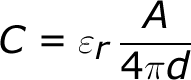
Where εr is the dielectric’s relative permittivity (a constant value determined by the dielectric material), A is the amount of area the plates overlap each other, and d is the distance between the plates.
How a Capacitor Works
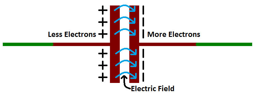
The positive and negative charges on each of these plates attract each other, because that’s what opposite charges do. But, with the dielectric sitting between them, as much as they want to come together, the charges will forever be stuck on the plate (until they have somewhere else to go). The stationary charges on these plates create an electric field, which influence electric potential energy and voltage. When charges group together on a capacitor like this, the cap is storing electric energy just as a battery might store chemical energy.
What makes capacitors special is their ability to store energy?
They’re like a fully charged electric battery. Caps, as we usually refer to them, have all sorts of critical applications in circuits. Common applications include local energy storage, voltage spike suppression, and complex signal filtering.
Dielectrics are insulators, plain and simple. The two words refer to the same class of materials, but are of different origin and are used preferentially in different contexts.
A dielectric material is a substance that is a poor conductor of electricity, but an efficient supporter of electrostatic fields. If the flow of current between opposite electric charge poles is kept to a minimum while the electrostatic lines of flux are not impeded or interrupted, an electrostatic field can store energy.
The capacitance is directly proportional to the surface areas of the plates, and is inversely proportional to the separation between the plates. Capacitance also depends on the dielectric constant of the substance separating the plates.
Capacitance Units
Not all capacitors are created equal. Each capacitor is built to have a specific amount of capacitance. The capacitance of a capacitor tells you how much charge it can store, more capacitance means more capacity to store charge. The standard unit of capacitance is called the farad, which is abbreviated F.
It turns out that a farad is a lot of capacitance, even 0.001F (1 milifarad – 1mF) is a big capacitor. Usually you’ll see capacitors rated in the pico- (10-12) to microfarad (10-6) range.
| Prefix Name | Abbreviation | Weight | Equivalent Farads |
|---|---|---|---|
| Picofarad | pF | 10-12 | 0.000000000001 F |
| Nanofarad | nF | 10-9 | 0.000000001 F |
| Microfarad | µF | 10-6 | 0.000001 F |
| Milifarad | mF | 10-3 | 0.001 F |
| Kilofarad | kF | 103 | 1000 F |
HOW I LEARNED?
Having a little background about this topic made it easier for me to understand but of course i still need more analyzed the circuit before making a move or have a solution
In this lesson it only proves one thing that there are still deeper things even if we already know about it. There are still a lot of lesson to learn.
Capacitors in Series and Parallel
Systems including capacitors more than one has equivalent capacitance. Capacitors can be connected to each other in two ways. They can be connected in series and in parallel. We will see capacitors in parallel first.
In this circuit capacitors are connected in parallel.

Because, left hand sides of the capacitors are connected to the potential a, and right hand sides of the capacitors are connected to the potential b. In other words we can say that each capacitor has same potential difference. We find the charge of each capacitor as;
Q1=C1.V
Q2=C2.V
Q3=C3.V
Total charge of the system is found by adding up each charge.
Qtotal=Ceq.V
Qtotal= Q1+Q2+Q3=C1.V+C2.V+C3.V=V.(C1+C2+C3)=Ceq
Ceq=C1+C2+C3
As you can see, we found the equivalent capacitance of the system as C1+C2+C3
Now we will see the capacitors in series;

In capacitors in series, each capacitor has same charge flow from battery. In this circuit, +Q charge flows from the positive part of the battery to the left plate of the first capacitor and it attracts –Q charge on the right plate, with the same idea, -Q charge flows from the battery to the right plate of the third capacitor and it attracts +Q on the left plate. Other capacitors are also charged with same way. To sum up we can say that each capacitor has same charge with batter.
C1.V1=Q
C2.V2=Q , V=V1+V2+V3 and Q=Ceq.V
C3.V3=Q

For example, In the circuit given below, C1=60µF, C2=20 µF, C3=9 µF and C4=12 µF. If the potential difference between points a an b Vab= 120V find the charge of the second capacitor.


REFLECTION
Connection… In this world everything has a connection from a single dot to another. We are all connected in some ways
Just like in our lives there are people we meet in parallel and some are in series. Parallel just like the people we pass by when we walk in the mall or in school. Or in series that we had a one path we are talking.
We are connected in many ways, just like our love ones, our family. We have a tie or connection that it is hard for anyone to cut. By this connection we have something to hold on when we feel like drowning, a connection that will help us to stand up and go on with life.
Its not always easy like we want too but we must know that we are not alone and we have a connection to hold on.
