Looking back from the first time we met each other, the first time you introduced Physics to us and in your presentation were you are introducing Physics I remember in the last slide, “pag hindi na talaga kaya, dasal-dasal na lang”. To be honest, I am really afraid of this subject and I will not deny the first meeting with Sir Lex I got intimidated by him. But what made me appreciate physics?
Honestly speaking, I really got a hard time in writing this one. I think of all the blogs that I’ve made this one is harder than I thought. I keep thinking what does Physics taught me? What did I get in this subject? Then I came to realize things.
It wasn’t easy learning Physics; you have to have a determination in knowing and understanding the concepts. A day is not enough to understand every lesson. There are some days “ay getsss!” and mostly “aniaa? Kasano kano?”.
Truly, it was not an easy one but who wants easy, right? Just like in our first activity and my first activity with my group mates, kung saan saan kami napunta bess! (tbh, napan kami pay likod math building) it was so frustrating and at the same time it was funny. The lesson is in Vector and the activity is to find the treasure that other section plant.
It was challenging, kinakapa ko pa mga ka grupo ko and it was not that hard naman. but in this activity i learned that in just one mistake you can get lost but the question is will you give up? No, the willingness of everyone from my group to find the treasure is one of the key why we try again and finally we got it.
From the start i know that Physics will not only teach me about Physics itself but also life lessons and realizations.
There are more activities like the free fall where we prove that all free-falling objects under influenced by gravity accelerate at the rate of 9.8 m/s² where i found out that no matter how light or heavy the object is it will fall at the same time.
This one taught me we might not be all the same, some might be lighter or heavier but we have our time, our own time.
There are still a lot of activities i hadn’t mention but all the activities we’ve done gave us the opportunity to experience on how the concept works. In projectile motion where it thought me to keep your feet on the ground whenever, whatever you may be, do not forget where you started. In inertia which make an object stop because we know that inertia is objects resistance to change, I can connect this to life where us must be not a barrier in other people’s dreams or goals in life. On torque were i can remember the scenario in school were determination represents torque that in order for us to achieve the goals we want in life there must be determination which will be our step in making our dreams. There are many more life lesson I’ve learned in physics but I think the others I will just keep it in my heart.
In making blogs, I must say it’s not easy. There are times that there are a lot of things to do, there is this also one time nagsabay sabay yung blog tas iba pang school work (deadsss) Sometimes pa I have to go to a place where wifi is fast and mama will picked me up after i finished my blog that time i really don’t know what to do first. I was asking God for his guidance. I don’t know but when you ask him talaga he will give you light, he will give you strength to go on.
I am also thankful for my classmates who willingly taught on what we don’t understand. My 2 years with them is a roller coaster ride, there are times the air in our room is pressured, disappointed in some things but we manage to go on and move forward. After a month or soon we will be crossing different paths in achieving our dreams. I know all of us will fly like the owl.
To Sir Lex, you did not only teach me us about Physics you also taught us to believe in ourselves, to give importance to little things. You gave us the opportunity to discover ourselves more. You give us activities not only for us to understand about the lesson but also to do team work, to communicate with our classmates. Secretly, I’m in aweee Sir! I feel so honored to be one of your students (no joke sir hehe). Maybe you don’t know me like the others but I assure you Sir, someday when I already reach my dreams I will never forget you. Thank you Sir and this isn’t a goodbye. I will still see you soon and maybe in the future I will get a chance to say to you “Sir syak ni Kisha nga estudyantem idi, registered nurse nakon”. If Plato, Socrates, Aristotle, Isaac Newton, Maxwell, Faraday and etc. contributed to the world by their concepts and inventions, You sir gave me inspiration that dreams will not end here that somewhere out there our dreams are waking at us. Thank you Sir not only for teaching us Physics and making STEM camp worth waiting for but also thank you for the life lessons.
“Physics
has shaped the world into what it is today” NEVER FORGET
I’m made of glass, this much is true. but when you look, you won’t see through. reflect on this, and you’ll find a clue!
Mirrors, i know most of us have like this in our homes. And for sure no day that we failed to stay in front and see our “reflection”. Reflection? It sounds familiar right? In terms of physics, what does really reflection mean? Lets find out.
What I Knew?
Honestly i do not know really that much about the reflection but of course when i hear the word reflection the first thing that always came to my mind is the mirror. Maybe we already tackled this one during on my lower grade levels but I can’t really remember.
What I Learned?
The capacity to learn is a gift; the ability to learn is a skill; the willingness to earn is a choice. -Brian Herbert
In this lesson i learned a lot. Of course i know some things on reflection but in here i learned about the concepts and law of reflection. New knowledge sometimes is not that easy to understand but with the help of our teacher and my group mates it somehow made things easier.
So let’s start discussing the things I learned in our class. First is on the Law of Reflection.
Law of Reflection
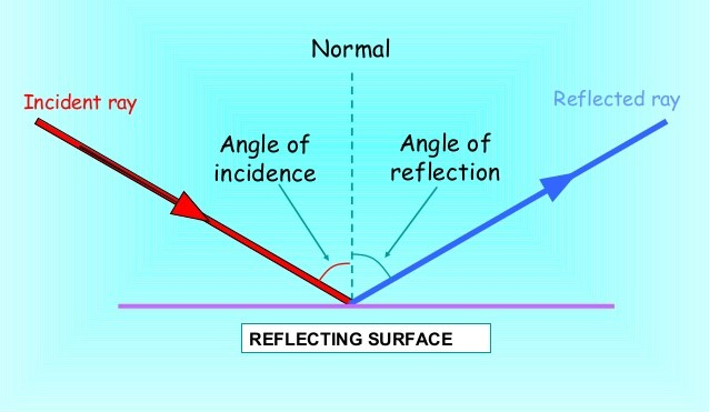
The law of reflection states that when a light ray is incident on a plane surface, then the incident ray, the reflected ray and the normal to the surface of the mirror all lie in the same plane.
In here it shows the light ray approaching the mirror is known as the incident ray, while the one that bounces off the mirror is called the reflected ray.
The straight line where the incident ray meets the mirror is called the “normal”.
ANGLE OF INCIDENCE
The angle between the incident ray and the normal
ANGLE OF REFLECTION
The angle between the reflected ray and the normal
POINT OF INCIDENCE
The point at which light falls.
LAW OF REFLECTION
The Angle of incidence is equal to the angle of reflection
i=r
>The law works for FLAT, PLANE surfaces only. >The angles are measured from a perpendicular line to the surface called a NORMAL.
The incident ray, refracted ray and the normal to the reflecting surface at the point of incidence lie on the same plane.
MULTIPLE REFLECTION
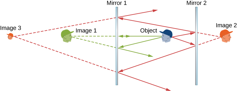
A mirror reflects everything in front of it including another mirror. If you place two mirrors at an angle, you increase the number of reflected images you can see. Depending on the angle you choose, you can see a number of unbroken reflections and one or more composite or partial reflections.
Increasing the number of flat mirrored surfaces or facets increases the number of reflections, but what you see depends on where you stand. The number of complete and partial reflections changes as you view the mirror from different angles.
Real image appears in front of the mirror (could be projected onto a screen)
Virtual – image appears behind the mirror
Enlarged – image is larger than the object Reduced – image is smaller than the object Same – image is the same size as the object
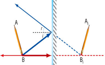
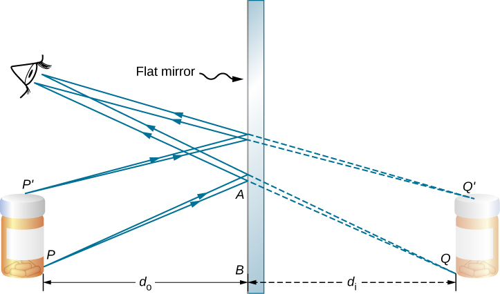
Image formation on plane mirrors
As you see from the picture we send rays from the top and bottom of the object to the mirror and reflect them with the same angle it hits the mirror. The extensions of the reflected rays give us the image of our object. The orientation and height of the image is same as the object. In plane mirrors always “virtual image” is formed.
Virtual image is an image formed by light that does not come from the image location (but it appears to come from the image)
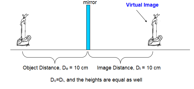
The distance between the image and the mirror is equal to the distance between the object and the mirror
Image formation on curved Mirrors
Concave Mirrors
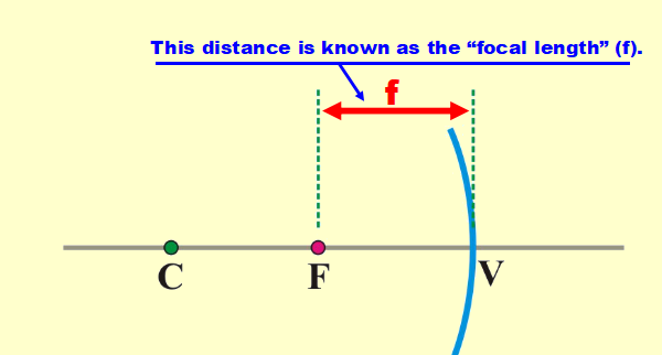
Since the mirror is spherical it technically has a CENTER OF CURVATURE, C. The focal point happens to be HALF this distance.
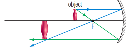
The characteristics of an image formed by a concave mirror depend on the location of the object. As it turns out, there are six “strategic” locations where an object may be placed. For each location, the image will be formed at a different place and with different characteristics.
Also called CONVERGING mirror
The focal length (f) is from the focal point (F) to the vertex point (V)
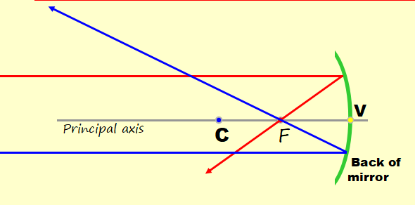
Ray Diagram
A ray diagram is a pictorial representation of how the light travels to form an image and can tell you the characteristics of the image.
A ray parallel to the principal axis is reflected through the focal point (F).
A ray that goes through the focal point (F) is reflected parallel to the principal axis.
Due to the great distance the object is from the mirror, all rays arrive at the mirror parallel to the principal axis.
As a result, all rays focus at the focal point and no image is formed.
Image is real, between C and F, inverted and reduced.
Object just beyond C
Image is real, located at C, inverted and same height as object.
Object at C
Image is real, located beyond C, inverted and larger than the object.
Object between C and F
All rays are reflected parallel and thus no image is formed.
Object at F
Image is virtual, located inside the mirror, upright and larger than the object.
Object between F and V (within the focal length)
Convex Mirrors
For convex mirrors, the image is always virtual, always located inside the mirror, always upright and always smaller than the object.
Also called DIVERGING mirror
The Mirror Equation
The mirror equation expresses the quantitative relationship between the object distance (do), the image distance (di), and the focal length (f).
The Magnification equation relates the ratio of the image distance and object distance to the ratio of the image height (hi) and object height (ho).
Here is how this works: If we get a POSITIVE magnification, the image is UPRIGHT. If we get a NEGATIVE magnification, the image is INVERTED If the magnification value is GREATER than 1, the image is ENLARGED. If the magnification value is LESS than 1, the image is REDUCED. If the magnification value is EQUAL to 1, the image is the SAME SIZE as the object.
Practical uses of the different types of mirrors
There are different types of mirrors made from different materials. When it comes to using mirrors, it is important to know the various types so you can make the most out of any mirror that you might have.
Plane Mirror
It has a flat or planar reflecting light rays in the order they are received. The virtual image that plane mirrors produce is the same size and distance as of the real objects. Though the image seen in a plane mirror will appear to be backward because it is reversed left to right.
In most of the measuring instruments, a plane mirror placed under the scale and pointer moves, the image in the plane mirror also moves.
Spherical Mirror
These can be concave or convex mirrors. A concave mirror has its glass plate curving inward similar to the way a teaspoon is curved and then coated with mercury. Concave mirror is bulge outward, similar to the back of a teaspoon.
Uses of Concave mirrors
It used in shaving to get an enlarged and erect image of the face.
Concave mirrors used in marine lighthouses that are found at the marine ports and seaports to guide the ships.
It is used in the solar furnaces to collect a large amount of solar energy in the focus of the mirror for cooking, heating water, recharging power backups or melting metals respectively.
It is used in front lights of cars to reflect the light.
Concave mirrors are using in telescopes; dentists use them to obtain a large image than the original teeth, ear or skin.
They also used in electron microscopes and magnifying glasses.
Flashlight of the camera uses this types of mirror.
Uses of Convex Mirrors
It is used as a side view mirror on the passenger’s side of a car because it forms an erect and smaller image for the way behind the car.
It is suitable for a convenient shop and big supermarkets and any other corner where need anti-thief.
It is used turning off the road and parking.
Vastly used in making lenses of sunglasses.
They can be used as street light reflectors because they can spread light over a big area.
One-Way/ Two-Way Mirrors
One way mirrors also known as two-way mirrors. They often associated with observation rooms and security applications where viewers on one side of the glass may look through the window without being seen on the other side.
These types of glass mirror effects are commonly seen on the television and in the movies.
Uses Of One Way/ Two Way Mirrors
Two way mirror used for security surveillance for example department stores or banks.
They used for monitoring work areas in offices, warehouses, and large stores.
It is used to protect hidden cameras.
It used in observation rooms where the distraction of onlookers maybe unwanted. For example daycare, dance schools, science labs.
How I learned?
As I said a while ago learning new things is not that easy. And learning and doing some activity is a great tool to help me understand more what the lessons talked about. I can say that doing activities with my group mates helps me a lot though in this activity we somehow argued but in a good way.
OBJECTIVES
To determine the relationship between the angle of incidence and the angle of reflection
To determine the relationship between the number of image reflection and the angle of separation
Angle of Reflection
Choose an angle using the protractor then put the push pins on it
Put another pushpin diagonal with the image created in the mirror.
Each member of the group choose the angle they want except for 90 and 180 degrees.
Angle of Separation
Place the pair of mirror on the origin of the Cartesian Plane based on its certain angles.
Put an object at the center.
Count the number of objects shown in the mirror
Findings from the Activity conducted
Angle of Separation
Angle of Reflection
Concave Mirror
OBJECT
L
O
S
T
15 cm
7 cm
Inverted
Reduced; hi= -1.5 cm
Real
10 cm
8.8 cm
Inverted
Reduced; hi= -2.5 cm
Real
7 cm
11.2 cm
Inverted
Enlarged; hi= -4.5 cm
Real
5 cm
No image
No image
No image
No image
3cm
5.5 cm
Upright
Enlarged; hi= 7.5 cm
Virtual
The Magnification equation relates the ratio of the image distance and object distance to the ratio of the image height (hi) and object height (ho) was use in this activity.
Reflection
Reflection… just like the mirror it reflects the things we put in front of it. Just like us, sometimes we need to reflect on ourselves, on the things we’ve done. We need to see things in not only one angle but it must be in different angles.
There are times where we see only one image, which we think its the only right thing that we almost forgot that we still have different angles to see new image, to see new things.
In this lesson, it does not only teach us about laws but it is also reminder to reflect on ourselves. Let’s not only focus into one angle, into one side. There are still other sides where things might be better.
Electromagnetism, upon hearing this word the first thing that came into my mind was magnet; it has the South and the North magnetic Pole. And also i remember our subject Electronics during our grade 10 days. We somehow touched some topics about electromagnetism.
What I learned?
In this lesson i know somehow i already have a clue on what the topic is all about because i got a slight background about this topic.
Let’s start discussing about the topics I learned in this lesson…..
On Electromagnetism this is the forces and fields with charge. It is also defined as the production of magnetic field by current flowing in conductor. There are two aspects of electromagnetism which is the electricity and magnetism, as when an electric current or a changing electric field generates a magnetic field, or when a changing magnetic field generates an electric field.
This arrangement is called a solenoid. The more turns we wrap on this core, the stronger the electromagnet and the stronger the magnetic lines of force become.
Electromagnets have become as a vital component in most of the electronic devices such as loudspeakers, motors, generators, magnetic separation equipment, hard disks, scientific equipment and much more. Its ability to turn magnetism on and off instantly is one of the important features responsible for its growing usage in modern electronic devices.
Even most of the home applications such as door bells, circuit breakers and music amplifiers in guitar use electromagnets to perform a wide range of functions. For example, when the button in the door is pushed electricity starts to flow over the electromagnet making it magnetic and clanging metal bell and metal clamp together causing a ringing sound. Once the button is released electricity flow shuts down thus, stopping the ringing sound.
With its amazing features, electromagnets have become as an integral part of modern technologies. Usually, electromagnets are made from coils of wire that carry electricity. When electricity flows through metal coil, electromagnets become magnetic and retain its magnetism until the current stops.
This illustration shows the magnetic field around a current-carrying wire. The current (capital letter “I”) is represented by the white arrow. The magnetic field (capital letter “B”) is represented by the red arrows
The right-hand rule, used to predict the direction of the magnetic field induced (or created) by a current. When you point the thumb on your right hand in the direction of current flow, your fingers curl in the direction of the magnetic field. If the current reverses direction, the magnetic field lines will also reverse direction.
Magnetic flux?
Magnetic flux is a measurement of the total magnetic field which passes through a given area. It is a useful tool for helping describe the effects of the magnetic force on something occupying a given area. The measurement of magnetic flux is tied to the particular area chosen.
The simplest example of induced electric field is the one generated inside a small circular conducting loop due to a changing magnetic field and responsible for the consequent current. Generally speaking, the induced electric field depends, not only on how the magnetic field, , changes with time, but also on how the geometric relation between the loop and magnetic field may change as well. The most basic definition is the magnetic flux through a plane figure due to a uniform magnetic field.
The vector labeled ‘normal’ is our unit vector , and the magnetic flux through the plane area is defined to be
Φ = BA
Faraday’s Law
In this law it states that any change in the magnetic environment of a coil of wire will cause a voltage (emf) to be “induced” in the coil. No matter how the change is produced, the voltage will be generated. The change could be produced by changing the magnetic field strength, moving a magnet toward or away from the coil, moving the coil into or out of the magnetic field, rotating the coil relative to the magnet, etc.
Faraday’s discovery in 1831 of the phenomenon of magnetic induction is one of the great milestones in the quest toward understanding and exploiting nature. Stated simply, Faraday found that a changing magnetic field in a circuit induces an electromotive force in the circuit; and the magnitude of the electromotive force equals the rate at which the flux of the magnetic field through the circuit changes. The flux is a measure of how much field penetrates through the circuit. The electromotive force is measured in volts and is represented by the equation.
Lenz’s Law
Lenz’s law is named after the German scientist H. F. E. Lenz in 1834. Lenz’s law obeys Newton’s third law of motion (i.e to every action there is always an equal and opposite reaction) and the conservation of energy (i.e energy may neither be created nor destroyed and therefore the sum of all the energies in the system is a constant).
Lenz’s law is based on Faraday’s law of induction.When a changing magnetic field is linked with a coil, an emf is induced in it. This change in magnetic field may be caused by changing the magnetic field strength by moving a magnet towards or away from the coil, or moving the coil into or out of the magnetic field as desired. Or in simple words, we can say that the magnitude of the emf induced in the circuit is proportional to the rate of change of flux.
Lenz’s Law
Lenz’s law states that when an emf is generated by a change in magnetic flux according to Faraday’s Law, the polarity of the induced emf is such, that it produces an current that’s magnetic field opposes the change which produces it. The negative sign used in Faraday’s law of electromagnetic induction, indicates that the induced emf ( ε ) and the change in magnetic flux (δΦB) have opposite signs.
Where, ε = Induced em δΦB = change in magnetic flux N = No of turns in coil
Law of Magnetic Poles
The most basic law of magnetism is that like poles repel one another and unlike poles attract each other; this can easily be seen by attempting to place like poles of two magnets together.
Further magnetic effects also exist. If a bar magnet is cut into two pieces, the pieces become individual magnets with opposite poles. Additionally, hammering, heating or twisting of the magnets can demagnetize them, because such handling breaks down the linear arrangement of the molecules. A final law of magnetism refers to retention; a long bar magnet will retain its magnetism longer than a short bar magnet.
How i learned?
In this lesson there are different laws that was teach by our teacher and in order for us to understand more he let us do an activity were he only gave us the materials and he let us discover and prove the relationship of induced emf and magnetic flux. in other groups they are also tasked to prove the relationship of induced emf and time, induced Emf and number of turn and lastly induced Emf and the negative sign in Lenz’s law.
Electromagnetic Induction
(Faraday’s Law and Lenz’s Law)
OBJECTIVE:
To prove Faraday’s Law and Lenz’s Law
(Identify the factors affecting the magnitude of induced emf.)
MATERIALS:
Magnets (3) with varying sizes
Solenoid
Galvanometer
Alligator Wires
Timer Ballpoint
Record Sheets
PROCEDURES:
Gather all the materials.
Connect the alligator wires to the galvanometer as well as the solenoid.
Using the connected galvanometer and solenoid, next is to insert one by one on the three different magnets (varying sizes) back and forth within 20 seconds.
Observe or identify the induced current of each magnet and record it in the record sheets.
RESULTS AND DISCUSSIONS:
Table 1. This shows the actual data and relationship between different sizes of magnets and induced emf.
Magnets(varying sizes)
Δt(time in seconds)
N(number of turns)
E(induced emf)
Long
20
100
300
Medium
20
100
200
Short
20
100
100
In this table it shows the relationship between the different sizes of magnets and induced emf (E). the magnet that has the longer in size has the highest induced emf and the shortest magnet has the lowest induced emf. This shows that the longer the size of magnet the greater the induced emf compared to the shorter magnet that has lower emf.
As the magnet moves back and forth, the pointer of the galvanometer moves. If we move the magnet back and forth continuously the pointer of the galvanometer moves also continuously. We also observed that the faster we move the magnet back and forth the higher the emf.
Table 2. This shows the actual data and relationship between magnetic flux and induced emf.
Magnets(varying sizes)
E(induced emf)
Φ(magnetic flux)
Long (Strong)
300
60
Medium (Moderate)
200
40
Short (Weak)
100
20
This table shows the relationship between magnetic flux (Φ) and induced emf (E). Time (Δt) and the number of turns of the coils (N) is constant. The strength of the magnets is based only by its size wherein it was assigned that the magnet 1 with the greater induced emf (300) was directly substituted in the formula Φ = which we derived it from the formula E = -N obtaining a value of Φ = 60. The other 2 magnets were also substituted in the said formula; magnet 2 with moderate induced emf came up with 40 magnetic flux and magnet 3 with lesser induced emf came up with 20 magnetic flux.
This proves that the induced emf (E) is directly proportional to the magnetic flux Φ. As the magnetic flux increases, the induced emf also increases and vice versa.
Additionally, magnets vary strengths in terms of materials, size and shape. One way to identify the strength of magnets is on how many objects can attract like for example the thumb tacks.
After gathering all our data this is not yet the end of the task. Our teacher let us visit also the different groups for them to explain and prove also the one that they are assigned to do.
On the relationship of induced Emf and number of turns is directly proportional to each other as the induced emf increases the number of turns also increases.
On the relationship of induced emf and time are inversely proportional to each other, this means that as the induced Emf increases the time decreases and vice versa.
On the negative sign this means that the induced Emf sends current in a direction so as to oppose the change in flux causing it.
Conclusion
Electromagnetism plays a vital role in our everyday life, there are thing that cannot work without it. Just like the generator, doorbells, speakers, computer hard drives, multiple household appliances and etc.These are just some examples of the things we use everyday using electromagnets. Imagine the computer hard drive without electromagnets, how students will be save their files? i just really don’t know.
In addition, this lesson I came to realize that not all things needs a complicated solution and answer. Just kike the task given to us, we overthink and some of the data that we found was not correct.
Finding the different relationship of the induced emf, time, magnetic flux and the negative N somehow a wake up call that not everything is complicated like we think, sometime it’s all about common sense.
Different aspects have different relationship, sometimes it can be directly or inversely. Just life, there are things that directly for us and inversely not for us that help us to grow more and find out what we are really up to.
All i know about capacitor is that it stores energy. When talking about capacitor we can also touch about the capacitance which is the one that permits the storage of energy.
WHAT I LEARNED?
A capacitor is a two-terminal, electrical component. Along with resistors and inductor, they are one of the most fundamental passive components we use. You would have to look very hard to find a circuit which didn’t have a capacitor in it.
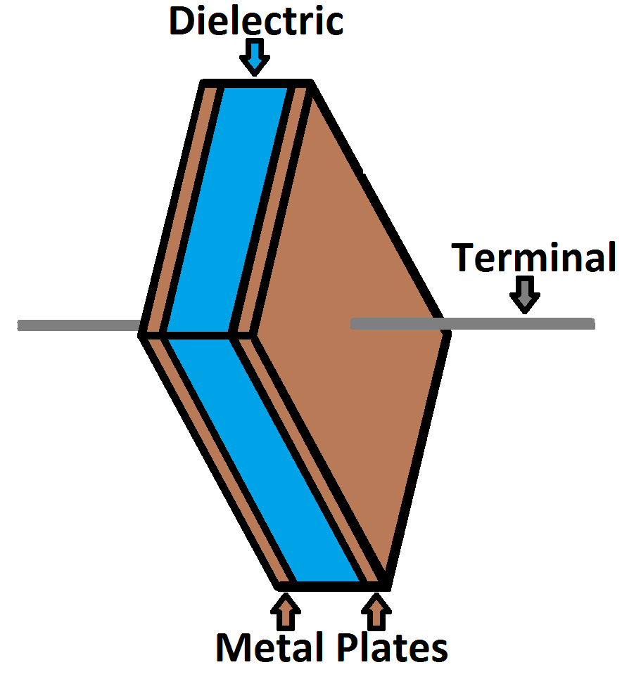
Capacitor is a passive electronic component that stores energy in the form of an electrostatic field. In its simplest form, a capacitor consists of two conducting plates separated by an insulating material called the dielectric.
How a Capacitor Is Made
The schematic symbol for a capacitor actually closely resembles how it’s made. A capacitor is created out of two metal plates and an insulating material called a dielectric. The metal plates are placed very close to each other, in parallel, but the dielectric sits between them to make sure they don’t touch.
Calculating Charge, Voltage, and Current
A capacitor’s capacitance – how many farads it has – tells you how much charge it can store. How much charge a capacitor is currently storing depends on the potential difference (voltage) between its plates. This relationship between charge, capacitance, and voltage can be modeled with this equation:
Charge (Q) stored in a capacitor is the product of its capacitance (C) and the voltage (V) applied to it.
The capacitance of a capacitor should always be a constant, known value. So we can adjust voltage to increase or decrease the cap’s charge. More voltage means more charge, less voltage…less charge.
That equation also gives us a good way to define the value of one farad. One farad (F) is the capacity to store one unit of energy (coulombs) per every one volt.
Calculating Current
We can take the charge/voltage/capacitance equation a step further to find out how capacitance and voltage affect current, because current is the rate of flow of charge. The gist of a capacitor’s relationship to voltage and current is this: the amount of current through a capacitor depends on both the capacitance and how quickly the voltage is rising or falling. If the voltage across a capacitor swiftly rises, a large positive current will be induced through the capacitor. A slower rise in voltage across a capacitor equates to a smaller current through it. If the voltage across a capacitor is steady and unchanging, no current will go through it.
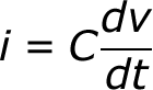
The equation for calculating current through a capacitor is:
The dV/dt part of that equation is a derivative (a fancy way of saying instantaneous rate) of voltage over time, it’s equivalent to saying “how fast is voltage going up or down at this very moment”. The big takeaway from this equation is that if voltage is steady, the derivative is zero, which means current is also zero. This is why current cannot flow through a capacitor holding a steady, DC voltage.
Capacitors in Series/Parallel
Much like resistors, multiple capacitors can be combined in series or parallel to create a combined equivalent capacitance. Capacitors, however, add together in a way that’s completely the opposite of resistors.
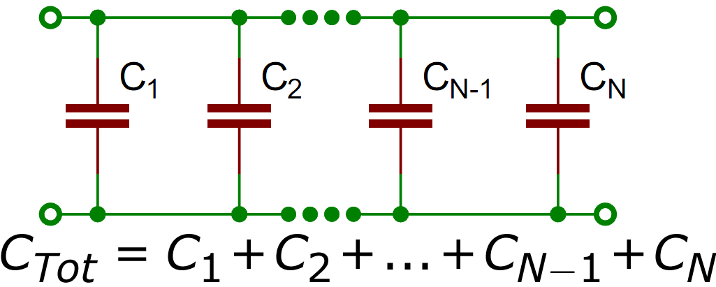
Capacitors in Parallel
When capacitors are placed in parallel with one another the total capacitance is simply the sum of all capacitances. This is analogous to the way resistors add when in series.
So, for example, if you had three capacitors of values 10µF, 1µF, and 0.1µF in parallel, the total capacitance would be 11.1µF (10+1+0.1).
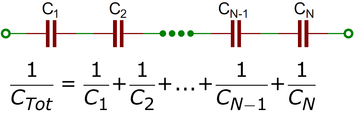
Capacitors in Series
Much like resistors are a pain to add in parallel, capacitors get funky when placed in series. The total capacitance of Ncapacitors in series is the inverse of the sum of all inverse capacitances.
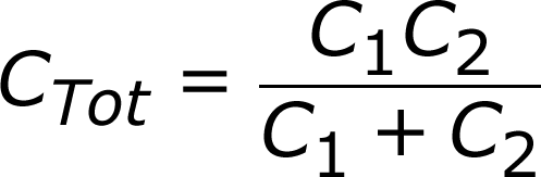
If you only have two capacitors in series, you can use the “product-over-sum” method to calculate the total capacitance:
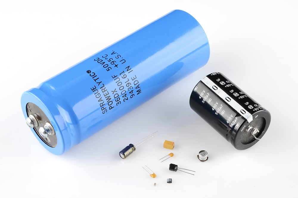
Types of Capacitors
There are all sorts of capacitor types out there, each with certain features and drawbacks which make it better for some applications than others.
When deciding on capacitor types there are a handful of factors to consider:
Size – Size both in terms of physical volume and capacitance. It’s not uncommon for a capacitor to be the largest component in a circuit. They can also be very tiny. More capacitance typically requires a larger capacitor.
Maximum voltage – Each capacitor is rated for a maximum voltage that can be dropped across it. Some capacitors might be rated for 1.5V, others might be rated for 100V. Exceeding the maximum voltage will usually result in destroying the capacitor.
Leakage current – Capacitors aren’t perfect. Every cap is prone to leaking some tiny amount of current through the dielectric, from one terminal to the other. This tiny current loss (usually nanoamps or less) is called leakage. Leakage causes energy stored in the capacitor to slowly, but surely drain away.
Equivalent series resistance (ESR) – The terminals of a capacitor aren’t 100% conductive, they’ll always have a tiny amount of resistance (usually less than 0.01Ω) to them. This resistance becomes a problem when a lot of current runs through the cap, producing heat and power loss.
Tolerance – Capacitors also can’t be made to have an exact, precise capacitance. Each cap will be rated for their nominal capacitance, but, depending on the type, the exact value might vary anywhere from ±1% to ±20% of the desired value.
The dielectric can be made out of all sorts of insulating materials: paper, glass, rubber, ceramic, plastic, or anything that will impede the flow of current.
The plates are made of a conductive material: aluminum, tantalum, silver, or other metals. They’re each connected to a terminal wire, which is what eventually connects to the rest of the circuit.
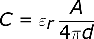
The capacitance of a capacitor – how many farads it has – depends on how it’s constructed. More capacitance requires a larger capacitor. Plates with more overlapping surface area provide more capacitance, while more distance between the plates means less capacitance. The material of the dielectric even has an effect on how many farads a cap has. The total capacitance of a capacitor can be calculated with the equation:
Where εr is the dielectric’s relative permittivity (a constant value determined by the dielectric material), A is the amount of area the plates overlap each other, and d is the distance between the plates.
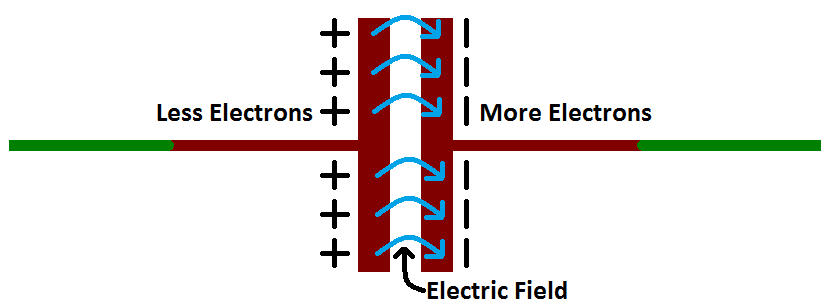
How a Capacitor Works
The positive and negative charges on each of these plates attract each other, because that’s what opposite charges do. But, with the dielectric sitting between them, as much as they want to come together, the charges will forever be stuck on the plate (until they have somewhere else to go). The stationary charges on these plates create an electric field, which influence electric potential energy and voltage. When charges group together on a capacitor like this, the cap is storing electric energy just as a battery might store chemical energy.
What makes capacitors special is their ability to store energy?
They’re like a fully charged electric battery. Caps, as we usually refer to them, have all sorts of critical applications in circuits. Common applications include local energy storage, voltage spike suppression, and complex signal filtering.
Dielectrics are insulators, plain and simple. The two words refer to the same class of materials, but are of different origin and are used preferentially in different contexts. A dielectric material is a substance that is a poor conductor of electricity, but an efficient supporter of electrostatic fields. If the flow of current between opposite electric charge poles is kept to a minimum while the electrostatic lines of flux are not impeded or interrupted, an electrostatic field can store energy.
The capacitance is directly proportional to the surface areas of the plates, and is inversely proportional to the separation between the plates. Capacitance also depends on the dielectric constant of the substance separating the plates.
Capacitance Units
Not all capacitors are created equal. Each capacitor is built to have a specific amount of capacitance. The capacitance of a capacitor tells you how much charge it can store, more capacitance means more capacity to store charge. The standard unit of capacitance is called the farad, which is abbreviated F.
It turns out that a farad is a lot of capacitance, even 0.001F (1 milifarad – 1mF) is a big capacitor. Usually you’ll see capacitors rated in the pico- (10-12) to microfarad (10-6) range.
Prefix Name
Abbreviation
Weight
Equivalent Farads
Picofarad
pF
10-12
0.000000000001 F
Nanofarad
nF
10-9
0.000000001 F
Microfarad
µF
10-6
0.000001 F
Milifarad
mF
10-3
0.001 F
Kilofarad
kF
103
1000 F
HOW I LEARNED?
Having a little background about this topic made it easier for me to understand but of course i still need more analyzed the circuit before making a move or have a solution
In this lesson it only proves one thing that there are still deeper things even if we already know about it. There are still a lot of lesson to learn.
Capacitors in Series and Parallel
Systems including capacitors more than one has equivalent capacitance. Capacitors can be connected to each other in two ways. They can be connected in series and in parallel. We will see capacitors in parallel first.
In this circuit capacitors are connected in parallel.
Because, left hand sides of the capacitors are connected to the potential a, and right hand sides of the capacitors are connected to the potential b. In other words we can say that each capacitor has same potential difference. We find the charge of each capacitor as;
Q1=C1.V
Q2=C2.V
Q3=C3.V
Total charge of the system is found by adding up each charge.
Qtotal=Ceq.V
Qtotal= Q1+Q2+Q3=C1.V+C2.V+C3.V=V.(C1+C2+C3)=Ceq
Ceq=C1+C2+C3
As you can see, we found the equivalent capacitance of the system as C1+C2+C3
Now we will see the capacitors in series;
In capacitors in series, each capacitor has same charge flow from battery. In this circuit, +Q charge flows from the positive part of the battery to the left plate of the first capacitor and it attracts –Q charge on the right plate, with the same idea, -Q charge flows from the battery to the right plate of the third capacitor and it attracts +Q on the left plate. Other capacitors are also charged with same way. To sum up we can say that each capacitor has same charge with batter.
C1.V1=Q
C2.V2=Q , V=V1+V2+V3 and Q=Ceq.V
C3.V3=Q
For example, In the circuit given below, C1=60µF, C2=20 µF, C3=9 µF and C4=12 µF. If the potential difference between points a an b Vab= 120V find the charge of the second capacitor.
REFLECTION
Connection… In this world everything has a connection from a single dot to another. We are all connected in some ways
Just like in our lives there are people we meet in parallel and some are in series. Parallel just like the people we pass by when we walk in the mall or in school. Or in series that we had a one path we are talking.
We are connected in many ways, just like our love ones, our family. We have a tie or connection that it is hard for anyone to cut. By this connection we have something to hold on when we feel like drowning, a connection that will help us to stand up and go on with life.
Its not always easy like we want too but we must know that we are not alone and we have a connection to hold on.
Honestly speaking i lack knowledge about this law but as far as i know we’ve already touched this lesson during our junior high school days but I can’t really remember.
WHAT I LEARNED?
Through the work of scientists in the late 18th century, the main features of the electrostatic force—the existence of two types of charge, the observation that like charges repel, unlike charges attract, and the decrease of force with distance—were eventually refined, and expressed as a mathematical formula. The mathematical formula for the electrostatic force is called Coulomb’s law after the French physicist Charles Coulomb (1736–1806), who performed experiments and first proposed a formula to calculate it.Coulomb’s Law
The electrostatic force is a vector quantity and is expressed in units of newtons. The force is understood to be along the line joining the two charges.
According to Coulomb, the electric force for charges at rest has the following properties:
Like charges repel each other; unlike charges attract. Thus, two negative charges repel one another, while a positive charge attracts a negative charge.
The attraction or repulsion acts along the line between the two charges.
The size of the force varies inversely as the square of the distance between the two charges. Therefore, if the distance between the two charges is doubled, the attraction or repulsion becomes weaker, decreasing to one-fourth of the original value. If the charges come 10 times closer, the size of the force increases by a factor of 100.
The size of the force is proportional to the value of each charge. The unit used to measure charge is the coulomb (C). If there were two positive charges, one of 0.1 coulomb and the second of 0.2 coulomb, they would repel each other with a force that depends on the product 0.2 × 0.1. Thus, if each of the charges were reduced by one-half, the repulsion would be reduced to one-quarter of its former value.
NOTE:
The Coulomb force is extraordinarily strong compared with the gravitational force, another basic force—but unlike gravitational force it can cancel, since it can be either attractive or repulsive.
The electrostatic force between two subatomic particles is far greater than the gravitational force between the same two particles.
HOW I LEARNED?
Really Physics is not that easy, there are a lot of courage and determination to better understand the lessons. It is true that we should understand first what is in the problem and what does the problem asking for. Through the help of Sir Lex and of course my classmates who understand the lesson first, I’ve got the chance to asked how did they come up with that answer, what is the formula to be used, and many more for me to better understand the lesson.
For example:
Two point-like charges carrying charges of +3×10⁻⁹ C and −5×10⁻⁹ C are 2 m apart. Determine the magnitude of the force between them and state whether it is attractive or repulsive.
Given:
Q1 = +3×10⁻⁹ C
Q2 = −5×10⁻⁹ C
r = 2 m
We know that k=9,0×10⁹ N·m2·C−2.
Determine the magnitude of the force
Using Coulomb’s law we have
F=k (Q1Q2)/r2=(9,0×109)(3×10−9)(5×10−9)(2)2=3,37×10−8 N
Thus the magnitude of the force is 3,37×10⁻⁸ N. However since the point charges have opposite signs, the force will be attractive.
Free body diagram
We can draw a free body diagram to show the forces. Each charge experiences a force with the same magnitude and the forces are attractive, so we have:
REFLECTIONI
This lesson is not really easy to understand, there are a lot of courage and willingness to learned in order to understand this lesson. Friends are really sometimes our heroes because of them I’ve got a helping hand of course also with our teacher.
I can relate this to the challenges in life, we encounter different obstacles in life but we must always have the will to find a solution.
As far as i can remember about electroscope is simply a charge-detecting device whether the charge is positive or negative. That the same charge repel and opposite charge attracts. And honestly speaking I don’t have enough knowledge about electroscope tho i know we somehow tackled this one in junior high.
What i learned?
Electroscope a kind of device for determining a charge in a body. It must be given an initial charge before it can be used to determine the charge of another body. Electroscopes generally give only a rough, qualitative indication of the magnitude of the charge.The electroscope may be charge either by conduction or induction.
Parts of Electroscope
Principle of Electroscope
The principle of an electroscope is based on the atomic structure of elements, the internal structure of metal elements, charge induction, and the idea that like charges repel and opposite charges attract. All elements are composed of electrons, protons, and neutrons – with the electrons surrounding the nucleus.
Conduction
Charging by conduction, both objects acquire the same type of charge. If a negative object is used to charge a neutral object, then both objects become charged negatively.
An example is when you walk to the door and you rub your feet, well that’s is charging by rubbing. And then when u touch the doorknob those charges on your hand are leaving you and there going into the doorknob. And that’s is called charging by contact.
Induction
Charging by induction, a charged object is brought close to but does not touch the conductor. In the end the conductor has charge of the opposite sign as the charge on the object.
Friction
Frictional charging process results in a transfer of electrons between the two objects that are rubbed together. For example, pumping gasoline through a hose at a gas station and when dry air rushes over the body of a car or an airplane, both can produce an electrical charge that can shock you if you were to touch the vehicle.
Just touching the hair with the comb allows the electrons to transfer but the rubbing allows more molecules to come in contact an in turn more electrons are transferred.
Additionally, material losing electron is positively charged and material gaining electron is negatively charged. Amount of gained and lost electron is equal to each other. In other words, we can say that charges of the system are conserved. When you rub glass rod to a silk, glass lose electron and positively charged and silk gain electron and negatively charged.charging by friction.
How I learned?
It was all started in the activity that was given to us by Sir Lex, the making of electroscope. Of course our group searched on the procedures on how to make an electroscope and how it works.
The main objective of the activity is to detect the presence and magnitude of electric charge on a body.
1.Start by putting a hole in the glass jar enough for the straw and copper wire to fit through.
2. Insert the straw into the hole and center it
3. Next, insert the copper wire into the straw.
4. Use the pliers to bend the copper wire into a hook to hold the aluminum foil later.
5. Use the pliers to bend the remaining copper on top of the lid into a coil to provide more surface area.
6. Next, cut a small slit in the aluminum foil and slide them onto the copper hook.
7. Attach the lid to the jar.
8. The electroscope is finished.
Reflection
“opposite do really attracts” This lesson really proves that not all objects that are the same come together, there are things that even they differ from each other they attracts. I can compare this to life which there are things that must be different in order for us to grow, to come out in our shells. just lie the people we met, we will meet. We differ from each other, we have different ideas, different types and etc. which make us learn from them that there are other things aside from the things that we know.
Waves appear in many forms and shapes. They have their own properties and behave differently from each other
Wave is a disturbance or variation which travels through a medium. They are characterized by wavelength, frequency, and the speed at which they move.
Standing waves don’t form under just any circumstances. They require that energy be fed into a system at an appropriate frequency
Parts of waves
Amplitude- the maximum positive displacement from the undisturbed position of the medium to the top of a crest.
Crest– section of the wave that rises above the undisturbed position.
Through– a section which lies below the undisturbed position.
Wavelength- wavelength of a wave is the distance between any two adjacent corresponding locations on the wave train.
Nodes and Antinodes
Node is a point along a standing wave where the wave has minimum amplitude.
Example:
In a vibrating guitar string, the ends of the string are nodes. By changing the position of the end node through frets, the guitarist changes the effective length of the vibrating string and thereby the note played.
Antinodes are where the amplitude (positive of negative) is a maximum, halfway between two adjacent nodes.
Harmonic Motion
Simple harmonic motion is typified by the motion of a mass on a spring when it is subject to the linear elastic restoring force given by Hooke’s Law.
The motion is sinusoidal in time and demonstrates a single resonant frequency.
Simple Harmonic Motion, maximum speed occurs at x = 0 (the equilibrium level or position), and speed is zero at the extreme ends ( x = +/- A ). Acceleration has a different story. At the middle (x = 0), acceleration is zero
The simple harmonic solution is
with being the natural frequency of the motion.
The period of a simple pendulum is
where is the length of the string and is the acceleration due to gravity
Types of Harmonic Motion
Mass Spring Oscillator
The simplest example of an oscillating system is a mass connected to a rigid foundation by way of a spring.
The spring constant k provides the elastic restoring force, and the inertia of the mass m provides the overshoot. By applying Newton’s second law F=ma to the mass, one can obtain the equation of motion for the system where is the natural oscillating frequency. The solutions to this equation of motion takes the form
where xm is the amplitude of the oscillation, and φ is the phase constant of the oscillation. Both xm and φ are constants determined by the initial condition (intial displacement and velocity) at time t=0 when one begins observing the oscillatory motion.
For a spring-mass system, such as a block attached to a spring, the spring force is responsible for the oscillation.
F_s = -kxFs=−kxF, start subscript, s, end subscript, equals, minus, k, x
Note: Calculate the time of one oscillation or the period (T) by dividing the total time by the number of oscillations you counted. Use your calculated (T) along with the exact length of the pendulum (L) in the above formula to find “g.”
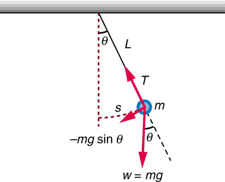
Simple Pendulum
A simple pendulum has a small-diameter bob and a string that has a very small mass but is strong enough not to stretch appreciably.
Simple pendulum consists of a mass m hanging from a string of length L and fixed at a pivot point P. When displaced to an initial angle and released, the pendulum will swing back and forth with periodic motion. By applying Newton’s second law for rotational systems, the equation of motion for the pendulum may be obtained
,and rearranged as
. If the amplitude of angular displacement is small enough that the small angle approximation () holds true, then the equation of motion reduces to the equation of simple harmonic motion
I like to challenge myself. I like to learn, so i like to try new things and try to keep growing. -David Schwimmer
This quotation can somewhat summarize what i knew before learning the the topics about Torque, Universal Law of Gravitation and Kepler’s Law of Planetary Motion.
What I Learned?
Let’s talk about Torque!
Torque is a measure of the force that can cause an object to rotate about an axis. Just as force is what causes an object to accelerate in linear kinematics, torque is what causes an object to acquire angular acceleration.
Torque is a vector quantity. The direction of the torque vector depends on the direction of the force on the axis.
For example, when a person opens a door, they push on the side of the door farthest from the hinges. Pushing on the side closest to the hinges requires considerably more force. Although the work done is the same in both cases (the larger force would be applied over a smaller distance) people generally prefer to apply less force, hence the usual location of the door handle.
Torque can be either static or dynamic
A static torque is one which does not produce an angular acceleration. Someone pushing on a closed door is applying a static torque to the door because the door is not rotating about its hinges, despite the force applied. Someone pedaling a bicycle at constant speed is also applying a static torque because they are not accelerating.
The drive shaft in a racing car accelerating from the start line is carrying a dynamic torque because it must be producing an angular acceleration of the wheels given that the car is accelerating along the track.The terminology used when describing torque can be confusing. The radius at which the force acts is sometimes called the moment arm.
The Equation for torque is:
τ=r×Fτ=r×F
where, F is the force vector, and r is the vector from the axis of rotation to the point where the force is acting. The units of torque are force multiplied by distance. The SI unit of torque is the Newton Meter. The most common English unit is the foot-pound.
The Universal Law of Gravitation
There is a popular story that Newton was sitting under an apple tree, an apple fell on his head, and he suddenly thought of the Universal Law of Gravitation.
The Law of Universal Gravitation states that every point mass attracts every other point mass in the universe by a force pointing in a straight line between the centers-of-mass of both points, and this force is proportional to the masses of the objects and inversely proportional to their separation. This attractive force always points inward, from one point to the other.
The Law applies to all objects with masses, big or small. Two big objects can be considered as point-like masses, if the distance between them is very large compared to their sizes or if they are spherically symmetric. For these cases the mass of each object can be represented as a point mass located at its center-of-mass.
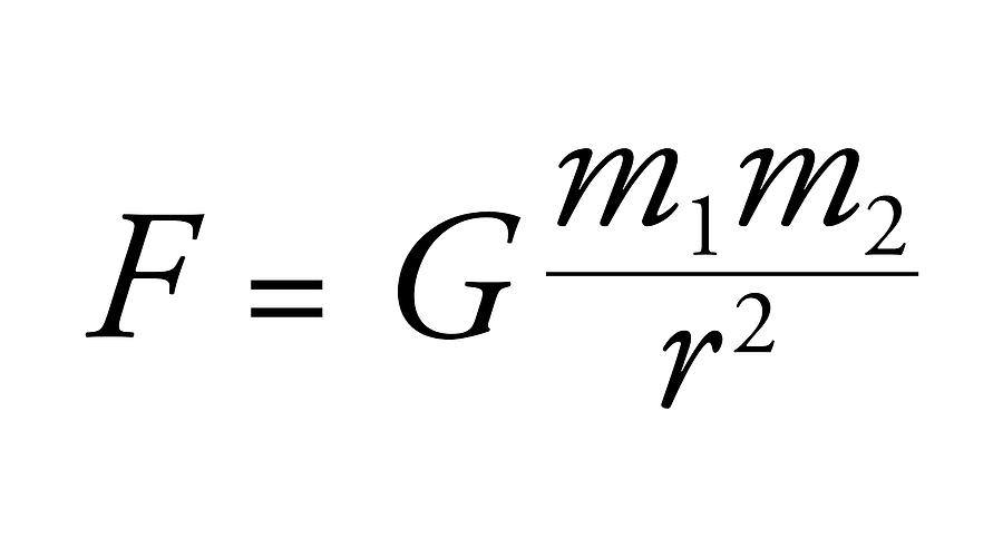
Equation which represents Newton’s law of universal gravitation
F = gravitational force of attraction (N)
m1, m2 are the interacting masses (kg)
r is the separation of the masses (m)
G is known as the universal gravitational constant. It sets the strength of the gravitational interaction in the sense that if it were doubled, so would all the gravitational forces.
G = 6.67 ´ 10-11 N m2 kg-2
Every object with a mass in the universe attracts every other according to this law. But the actual size of the force becomes very small for objects very far away. For example, the Sun is about one million times more massive than the Earth, but because it’s so far away, the pull on us from the Sun is dwarfed by the pull on us from the Earth.
As the separation of two objects increases, the separation increases even more, dramatically. The gravitational force will decrease by the same factor (since separation appears in the denominator of the equation).
Weight and the Gravitational Force
We have seen that in the Universal Law of Gravitation the crucial quantity is mass. In popular language mass and weight are often used to mean the same thing; in reality they are related but quite different things. What we commonly call weight is really just the gravitational force exerted on an object of a certain mass. We can illustrate by choosing the Earth as one of the two masses in the previous illustration of the Law of Gravitation:
Thus, the weight of an object of mass m at the surface of the Earth is obtained by multiplying the mass m by the acceleration due to gravity, g, at the surface of the Earth. The acceleration due to gravity is approximately the product of the universal gravitational constant G and the mass of the Earth M, divided by the radius of the Earth, r, squared. (We assume the Earth to be spherical and neglect the radius of the object relative to the radius of the Earth in this discussion.) The measured gravitational acceleration at the Earth’s surface is found to be about 980 cm/second/second.
The inverse square law proposed by Newton suggests that the force of gravity acting between any two objects is inversely proportional to the square of the separation distance between the object’s centers. Altering the separation distance (r) results in an alteration in the force of gravity acting between the objects. Since the two quantities are inversely proportional, an increase in one quantity results in a decrease in the value of the other quantity. That is, an increase in the separation distance causes a decrease in the force of gravity and a decrease in the separation distance causes an increase in the force of gravity.
Furthermore, the factor by which the force of gravity is changed is the square of the factor by which the separation distance is changed. So if the separation distance is doubled (increased by a factor of 2), then the force of gravity is decreased by a factor of four (2 raised to the second power). And if the separation distance (r) is tripled (increased by a factor of 3), then the force of gravity is decreased by a factor of nine (3 raised to the second power). Thinking of the force-distance relationship in this way involves using a mathematical relationship as a guide to thinking about how an alteration in one variable effects the other variable.
The proportionality expressed by Newton’s universal law of gravitation is represented graphically by the following illustration.
In the above figure, the figure on the left hand side indicates the effect of “mass” if the distance between the two objects remains fixed at a given value “d”. The right hand figure shows the effect of changing the distance while keeping the mass constant, and the last part of it shows the effect of changing both the distance and the mass.
Kepler’s Law of Planetary Motion
Johannes Kepler, working with data painstakingly collected by Tycho Brahe without the aid of a telescope, developed three laws which described the motion of the planets across the sky.
1. The Law of Orbits: All planets move in elliptical orbits, with the sun at one focus.
2. The Law of Areas: A line that connects a planet to the sun sweeps out equal areas in equal times.
3. The Law of Periods: The square of the period of any planet is proportional to the cube of the semi major axis of its orbit.
Kepler’s laws were derived for orbits around the sun, but they apply to satellite orbits as well.
The Law of Orbits
All planets move in elliptical orbits, with the sun at one focus.
This is one of Kepler’s Law. The elliptical shape of the orbit is a result of the inverse square force of gravity. The eccentricity of the ellipse is greatly exaggerated here.
Orbit Eccentricity
The eccentricity of an ellipse can be defined as the ratio of the distance
between the foci to the major axis of the ellipse. The eccentricity is zero for a circle. Of the planetary orbits, only Pluto has a large eccentricity
The Law of Areas
A line that connects a planet to the sun sweeps out equal areas in equal times.
This is one of Kepler’s Laws.This empirical law discovered by Kepler arises from conservation of angular momentum. When the planet is closer to the sun, it moves faster, sweeping through a longer path in a given time.
How I Learned?
Learning new things can be somewhat hard to really understand, sometimes it’s just the matter of time to realize what it is really meant.
Having knowledge about these topics made me “aweee’s and owemgiee” nevertheless it was all a good topic.
For me, the way our teacher explains our lesson has a big impact to better understand the topics, showing us visuals, solving on the board, letting us do some exercises and of course asking us if we understand the lesson.
One way for us to better understand the lesson was our teacher gave us an activity to work on
In this activity we are task to draw and make our own planet. And solved the semi major axis. And in the drawing we also put labels so that it will be more clearer to understand what part of the orbit is that.
Reflection
The more torque I can come up with, the better.
-Anne Sweeney
The more force it gives the better. We know that torque is a measure of the force that can cause an object to rotate. The first thing that came into my mind was a scenario in school were determination represents torque that in order for us to achieve the goals we want in life there must be determination which will be our step in making our dreams. Torque can also be the sacrifices of our parents for us, for us to be a better person one example is them letting us go to school for our future, for our own benefits.
Good day! In this journal I will be talking about moment of inertia and rotational motion.
WHAT I KNOW
Seriously talking, upon hearing moment of inertia the first thing that came to my mind is Newton’s Law that is a property of matter that causes it to resist changes in velocity. According to Newton’s first law of motion, an object with a given velocity maintains that velocity unless acted on by an external force. Simple
WHAT I LEARNED
Moment of Inertia
Moment of Inertia is nothing but a quantity expressing a body’s tendency to resist angular acceleration, which is the sum of the products of the mass of each particle in the body with the square of its distance from the axis of rotation. Additionally, Angular Acceleration means Angular Acceleration, also called Rotational Acceleration, it’s a quantitative expression of the change in Angular Velocity that a spinning object undergoes per unit time. It is a vector quantity, consisting of a magnitude component and either of two defined directions or senses.
For example, a body when it starts rotating it will keep doing so until we try to to stop it by a force(torque). It’s like if we have a football and a solid sphere which are both rotating with the time frequency, one will stop by applying more torque while the other will stop easily. The one stopping easily has higher moment of inertia. It is the equivalent of mass in rotational motion . There we need more force to stop a body with higher mass.
Four objects with identical masses and radii racing down a plane while rolling without slipping.
From back to front:
spherical shell (red),
solid sphere (yellow),
cylindrical ring (green), and
solid cylinder (red)).
The time for each object to reach the finishing line depends on their moment of inertia.
Note: Sphere always win and Hollow objects always lose!
Analogs for Rotational Motion
The Torque Construct: The Rotational Analog to Force
Consider a force F exerted tangentially on the rim of a wheel or disk. The rim is at a distance r from the axis of rotation. We can formally define torque, represented by the Greek letter ττ , in terms of the force F and the distance r:
where r is sometimes referred to as the moment arm of this applied force—the further away from the axis a particular force is applied, the more torque is exerted, producing more change in rotational motion. Torque can be thought of as the “turning effectiveness of a force” or “rotational force.”
This force can be broken down into its tangential and radial components, FtangentialFtangential and FradialFradial. Note that the radial component FradialFradial of this force has no effect on the rotational motion of this disk. So, for any general force exerted a distance r from a rotation axis, it is only the tangential component of this force (Ftangential)(Ftangential) that will affect rotational motion. The tangential component of the force can always be found with the appropriate trig function. If θθ is the angle between the applied force, F, and r, the tangential component is FsinθFsinθ .
Torque, along with other angular variables, has vector properties. If we imagine the torque causing the object to rotate about an axis perpendicular to the plane defined by the force and the moment arm, rr , we can use the same right-hand-rule introduced for finding the direction of θθ and ωω to find the direction of the torque ττ . If you curl the fingers of your right hand in the direction of rotation that the torque would cause, then your thumb points in the direction of the torque.
Sample Problem
A marble is thrown with velocity V from point A. If no force is exerted on surface by marble at point B, find the force exerted on point A by marble. (Assume that velocity of marble is constant.)
Since no force is exerted on point B by marble;
mg=mV2/R
V2=g.R
Force exerted by marble on point A;
FA=G+F
FA=mg+mV2/R (we put V2=gR into the equation)
FA=mg+mgR/R
FA=2mg
AngJext=τavgΔt(7.5.10)(7.5.10)AngJext=τavgΔt
HOW I LEARNED
Learning new things in creative ways is somehow help us students to understand more about the lesson. One way that Sir Lex did was to show us a video presentation of Walter Lewin about The concept of moment of inertia that is demonstrated by rolling a series of cylinders down an inclined plane.
Another one is the activity that Sir Lex let us experience, he let us decide and design the object that our group will use. my group decided to use a solid sphere and the other one is the tissue roll. And luckily our group won the challenge to be the fastest among other group and so with the slowest to roll.
This part is where we won in the fastest one to roll and the first one to reach the white line.
And this one is where we won the slowest one to reach the white line.
REFLECTIONS
There are many cross roads and bumps in every person’s life. There are many challenges that can make us stronger and make us understand life. In connection to moment of inertia which make an object stop because we know that inertia is objects resistance to change, I can connect this to life where us must be not a barrier in other people’s dreams or goals in life.
Let’s not be insensitive to other people, there are things we must do and not to do.
To be honest I’m not sure if we’ve touched about projectile motion during our early years in high school because I’m not really that sure about Projectile Motion or I just did forgot about this topic.
Before I’m gonna tell what i learned about projectile motion, I want to share my readings about the history of projectile motion, so there are two names that appear in my readings, Aristotle and Galileo. Aristotle’s theory of motion, projectiles were pushed along by an external force which was transmitted through the air while Galileo he figured out that a projectile has two motions, instead of just one. He also said that “the motion that acts vertically is the force of Gravity”, which pulls the object back down to earth at 9.8 meters per second, and that “while gravity was pulling the object down to Earth, the projectile was also moving horizontally at the same time”.
For further understanding,
drawing is by Niccolo Tartaglia
This illustration reflects the general opinion of projectile motion before Galileo. The theory was based on Aristotle’s views of motion and held that a shot object (a cannon ball, for example) followed a straight line until it “lost its impetus,” at which point it fell abruptly to the ground.
Later, Galileo realized that projectiles actually follow a curved path. Galileo said that projectile motion could be understood by analyzing the horizontal and vertical components separately.
drawing is by Niccolo Tartaglia
Galileo understood that the projectile’s path is a combination of horizontal and vertical motion.
Galileo understood that vertical motion does not affect horizontal motion.
An object projected horizontally will reach the ground in the same time as an object dropped vertically. No matter how large the horizontal velocity is, the downward acceleration is always the same.
Gravity accelerates an object downward even if it is moving horizontally
PROJECTILE MOTION
So What did i learned? I did learned that projectile motion is any object that the only force acting on it is gravity and air resistance is negligible. Another definition is the free fall motion of any object in a horizontal path with constant velocity (air resistance is negligible). The body in motion is called projectile. And the path of the projectile is called trajectory.
Two components of projectile motion
An object moves forward due to the initial applied force and then just inertia.
An object accelerates downward due to gravity.
NOTE: The most important fact to remember is that motions along perpendicular axes are independent and thus can be analyzed separately. Where vertical and horizontal motions were seen to be independent. The key to analyzing two-dimensional projectile motion is to break it into two motions, one along the horizontal axis and the other along the vertical.
Equations that can explain more about the Projectile Motion
Types of Projectile Motion
HORIZONTAL
Motion of the ball rolling freely along a level surface area
Horizontal velocity isALWAYS CONSTANT
VERTICAL
Motion of freely falling object
Force due to gravity
Vertical component of velocity changes with time
PARABOLIC
Path traced by an object accelerating only in the vertical direction while moving at the constant horizontal velocity.
Example:
Throwing the ball straight upward, or kicking a ball and give it a speed at an angle to the horizontal or just drop things and make them free fall.
The example shows that regardless of whether a projectile is moving downwards, upwards, upwards and rightwards, or downwards and leftwards and air resistance is negligible it is still projectile as long as it continues in motion by its own inertiaand is influenced only by the downward force of gravity.
Another Illustration
Once the object leaves the table, it experiences a downward acceleration equal to gravity (9.8 m/s/s). Thus the vertical velocity (Vy) is continually increasing. The horizontal velocity (Vx) remains constant and is equal to Vxo. The two vectors Vx and Vy are added together to get the velocity at each point on the path.
If an object is pointed at an angle, the motion is essentially the same except that there is now an initial vertical velocity (Vyo). Because of the downward acceleration of gravity, Vy continually decreases until it reaches its highest point, at which it begins to fall downward.
Additionally, I learned that not all moving upward objects must have an upward force so with moving rightward or vice versa. Force is is not required to keep an object in motion.A force is only required to maintain an acceleration. And in the case of a projectile that is moving upward, there is a downward force and a downward acceleration.
Sir Lex gave us a video to watched at home, yes it is a flipped classroom. The video is about the concepts of Projectile motion using car driving off in a cliff as an example and the other video is a Projectile Practice Problem. For me the video is very helpful, the visual really made me understand what is all about the concepts. The video is just one of the tool that help me understand the projectile motion.Although I admitted that i got confused in the situational test that Sir Lex gave us, I learned that trust really your instincts (wow!) and do not change your first answer. The other one is the activity that we did, which we made our own catapult.
So here it is.
Ready the catapult for ONE BIG FIGHT!!
So after preparing the catapult and releasing it, hoping for the farthest one. And some of our group member started to measure how far the marshmallow went to.
Sugod lang bes kahit matingkad ang araw para sa Physics
Physics can make you and break you (hugot agad) but really I think it’s true that physics can make and break you at the same time. Make you in a sense that if you can follow the lesson well it’s an achievement it is very fulfilling. And of course break you if you will not listen and you cannot follow the lesson (dasal-dasal na).
Keep your head high but keep your feet on the ground this is one of the lesson that projectile motion thought me because we will all start with our own different path but some will go higher, some will go straight and faster that you are but everything will takes time, everything has its own timing but we must not forget that not everything will go the way we want to be, we will not always be on top, in the middle or just down there. But whatever it is gravity will keep us on the ground and it will remind us how we all started.


 being the natural frequency of the motion.
 is the length of the string and
  is the acceleration due to gravity
 ,
, .
. ) holds true, then the equation of motion reduces to the equation of simple harmonic motion


You must be logged in to post a comment.